Yesterday was the ever exciting Wednesday meeting. We all rushed through it in hopes of getting to the more substantial notes review of the ETC Submital
Thursday, June 28, 2007
Monday, June 25, 2007
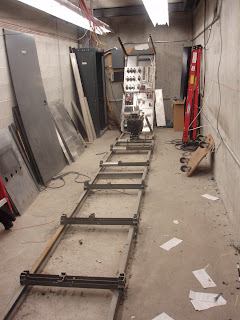
Cement walls
Here we are looking at the cement wall where the patch panel once was. This is good we are going to need storage space for our new choral risers and our new platforms that are coming. Looks like it 8' x 4 ' just enough space for our special cart to sit.
Pit Controller works fine
I don't know why but after all that the pit controller works fine throught the Stage Right wall receptacle. So that is good and all we have to do is cap that off and say that the drawings were right and the added stuff just made it confusing without changing the original.
Friday, June 22, 2007
Pit Lift Controller
For all those interested in this question. The drawing indicates that the 1" conduit from the controller box under the pit goes directly to he wall mounted receptacle on Stage Right. The conduit holding the control lines down there also turns in that direction as it goes into the concrete slab. Now i am wondering if the power line #22 just doesn't work there and it has been that way for some time. My feeling is that the control lines from the pit go to the recptacle stage right and then continues to SMP 01 then over to SMP 02. But since the power wasn't working when they added the two extra receptacles they decided to just pull the power from the Main Curtain controller
Maybe. But here is the drawing indicating the conduit run to SR
Oh thats why it wouldn't work
the picture below shows the extensive carbon and burn marks left inside the channels. Especially in this segment that was near the non dims track
dimmer room is almost empty
The dimmer room is close, Anyone need a paperweight??
yesterday the camera broke
&uot
[ so cleary the images are messed up and i can't seem to move this one down to the bottome but this image is the comparison to the one at the bottome. This image is after i put the camera back together]


Yesterday the camera fell to the ground. It was what seemed a rather insignificant event until the end to the day when i was writing this blog and uploading my pictures. The images from the end of yesterday, as you can see from the blog are all out of focus and very bad images. I inspected the camera and could see that the decorative plastic ring that went around the lens had dented. This made me feel that the warranty was useless since it was from some sort of impact that the problems were created. One could argue that a point and shoot camera that can't survive a fall to the floor from 5 feet up is a design flaw but i don't think the warrarnty cares much for that argument.
so the problem.
In the investigation as to what could have happened to the camera it became most apparent when you zoomed forward and the image was filled with this curve. So either the lens or the sensor was knocked out of place. The retracting of the lens when turned on and off was still working fine. It opened and closed without an apparent problem no weird sounds that might indicate that the motor was working harder so that made me think that maybe the sensor had been knocked out of alignment.
Here is an image from when i was trying to figure out that something was wrong with the camera.
[ so cleary the images are messed up and i can't seem to move this one down to the bottome but this image is the comparison to the one at the bottome. This image is after i put the camera back together]
So on realizing that if i wanted to use the camera i was going to have to fix it myself since the warrenty wouldn't apply and insurance was not implemented. Â (I only got the camera two weeks ago).
So started to take the camera apart hoping i could find the thing that was out of alignment. As it came apart it, of course got more and more complicated and my system for keeping track of the tiny screws quickly deterioted into a lot of tiny screws sitting on my desk. So like the lighting project i was at a point of no return. It seemed like i was heading towards nothing working. By the end of the day i had figured out the sensor situation and that was not the problem so i had to go back to the lens but no adjustment to that part seemed to do anything. So i needed to get past the sensor to the lens that sits right in front of the sensor. The great thing about this small camera is that since it is so small the sensor has to move to the left when the camera compacts to its off position. That means springs and more motors to move peices of plastic. I had to get passed this moving plastic frame that held the senor to see into the lens mechanism. More small screws were on the table. There was some sort of glass peice that was between the sensor and the lens so i tried to grab this out but instead it fell out of site into the open lens area. Nice! So that was the end of that. Turning the thing upside down didn't do anything to get this glass thing out. So i left for the day thinking that the blog was over.............................................
Today i took out more screws and was able to see the lens that was on this side and the glass that had fallen in. emptied out all the parts and then powere the camera back up to close the lens again. The lens that was on this side seemed wonky so i tried to adjust it to see it anything would happen. Somthing happened but i couldn't tell what. So i thought when i have a chance i will try and close this thing back up.
Eventually after giveg up hope i closed the thing and i am left with five screws. But then i turned it on here is the picture i got......
So somehow after taking this thing apart i managed to get it back to together. Beyond all odds. Even Matt thought it was a lost cause and the camera was useless. I wish i had a picture of the desk with this thing splayed out but alas the innards made it hard to use the sensor.
Thursday, June 21, 2007
Updating today, tomorrow aggresion will be had all invited
Dimmer room continues to spill it's guts out. There are a lot of hex nuts to deal with.
now there is just the little 7 volt problem
But it seems the power is not passing through but ganged together with the outlet
Weird, So back to the transformer on the other side of the wall. IF we meter it and start turning off all the things that have 240 maybe it will turn off. Nope, but the outlet we have been looking through is labeled 8 so lets turn off 8. There it is, half of our 240 is coming off of the 8 breaker. Now we have to find the other leg. Lets try the next breaker down 10. Yep there it is if 8 and 10 are on then the transformer has full power of 24 volts. both 8 and 10 have no indication that they may be ganged together or that they may be powering the audience call system. But now we have found it and the SMP has been tested to have no more errant voltage.
120 volts still in Stage Manger Panel
So this is the amazing SMP (stage manager panel). This one is actually the #1 panel there is a sub panel on SL but it doesn't have all of the buttons. So the goals was to make sure no more voltage was running through any of these wires. An interesting task considering rats nest that is in here. Ryan spent most of the day after the meetings trying to run down the circuits and the breakers that would turn off the errant voltage. At around 3 pm i joined him on the last two errant voltages. A 7 volt that was going to the audience call bells in front of house and then the 120 volts that were still coming to the third terminal strip that you can see mounted in the back.
So after flipping all the breakers in G2 panel and none of them cut our power Ryan came back and we started pulling more cables and trying to see which conduit our grey wire was going into. It seemed to be going into a conduit that crossed the stage. During this time Ryan discovered the terminal switches had a label that had fallen out of the way so held it back up and discovered that it was labeled PL 22.
What is PL 22? Our first thought was Plaster line. But what could that be. the outlets on the lip of the stage? No but then we headed over to the other sub SMP and that one had a lot less cables. The brown 22 cable was easier to follow and on of the leads ended on the other side of this connector installed in the bottom of the box. So suddenly PL became Pit Lift. Only a we always called it the pit elevator so the L didn't make sense until we found it terminating in this connector
So now back to the drawing to try and follow the Pit Lift lines. Now it gets interesting turning off what seems like the pit lift controller under the lift doesn't make us loose the power in the SMP box. So where is the Pit Controller getting its power. Ryan goes on a hunch to room 59 L (Dougs old office) where there is a panel that used to have the power for the main curtains motor power and controller power. By flipping off the breaker for the Main Curtain Controller (which was no longer used since we don't have that motor or those buttons in the SMP any more) it turned off the terminal. So there it is...the power to the controller had been routed through the now defunct main curtain controller.
Wednesday, June 20, 2007
dimmer room
Subscribe to:
Posts (Atom)